This post will cover how to configure Palo Alto site-to-site VPN with Cisco ASA. However, the post will not cover any of the ASA configuration parts, but please check out Cisco documentation on this link if required. Configuring a site to site VPN tunnel on Palo Alto firewalls is not difficult, but it could be a little bit challenging for the people who are not familiar with Palo Alto UI. I think the main challenge would be where to find some of the settings that could be nested into others.
By default Palo Alto firewalls use route-based VPN, but we can change this to be policy-based VPN if required with just a couple of minor changes, you will go through them in this lab. In our lab we are going to configure the Palo Alto site-to-site VPN with Cisco ASA using IKEv1. Let's get started!
Step 1: IKE Crypto
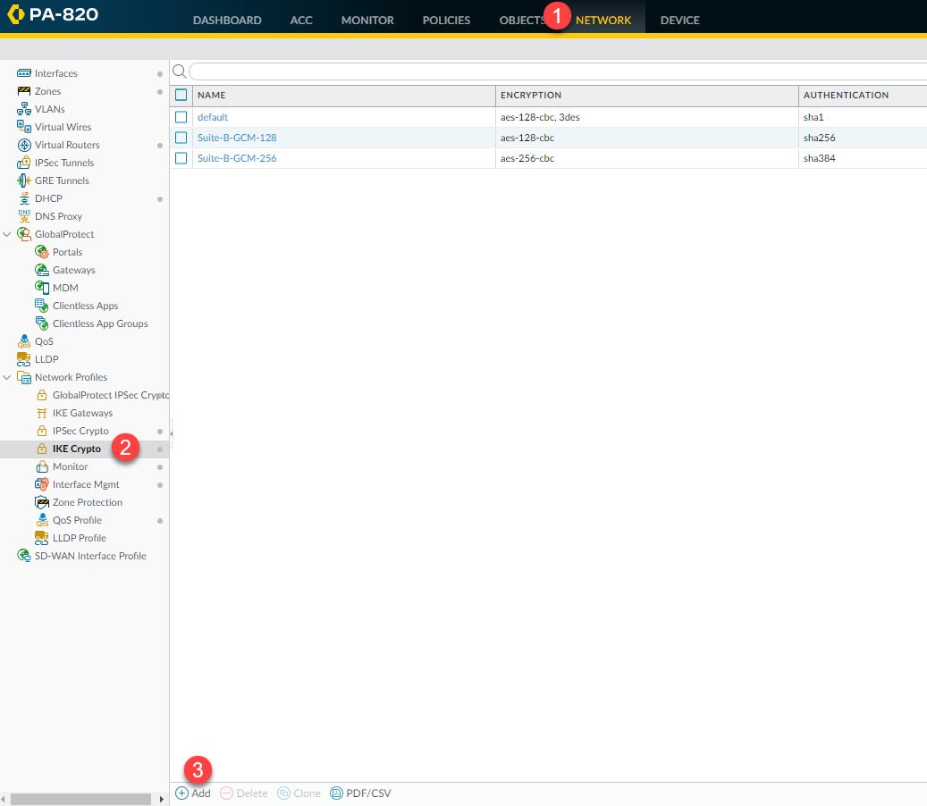
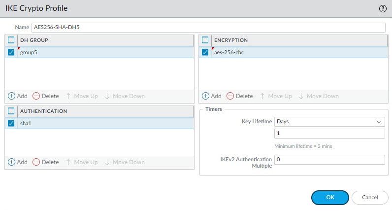
In this step we are going to create our Phase 1 IKE profile to define the DH group, authentication and encryption algorithms, and the Phase 1 lifetime. In the next step we will associate this profile to the IKE Gateway that will tie all the Phase 1 settings together.
Go to Network > Network Profiles > IKE Crypto > Add
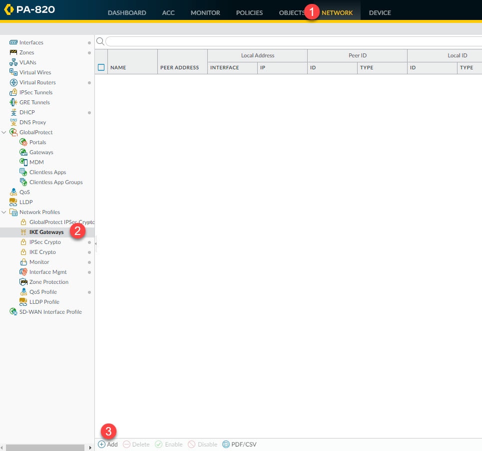
Step 2: IKE Gateways
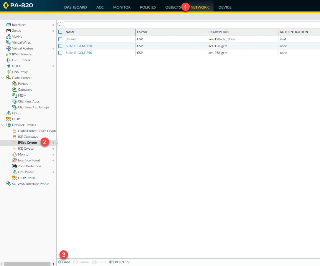
Go to Network > Network Profiles > IPSec Crypto > Add
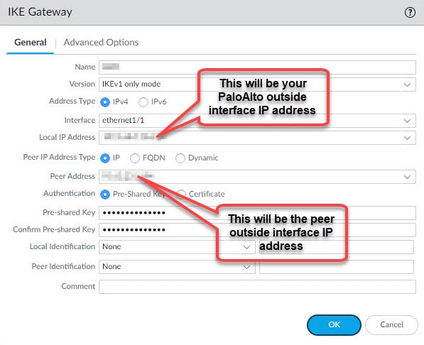
Give the IKE Gateway a name, select the outside interface of the Palo Alto firewall and select the outside interface IP address. If the outside interface has only one single IP then you can leave the Local IP Address blank, in that case its IP address will be used by default. Define the Local IP Address, Peer Address, the pre-shared key, and then move to Advanced Options tab.
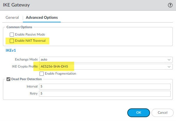
In the Advanced Options tab select the IKE Crypto profile we created in the previous step, and if DPDs are enabled on the ASA leave that box checked.
Step 3: IPSec Crypto
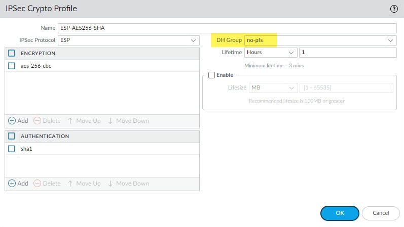
In this step we will define the Phase 2 settings such as the IPSec protocol, encryption and authentication algorithms and PSF if used.
Go to Network > Network Profiles > IPSec Crypto > Add
Step 4: Interfaces
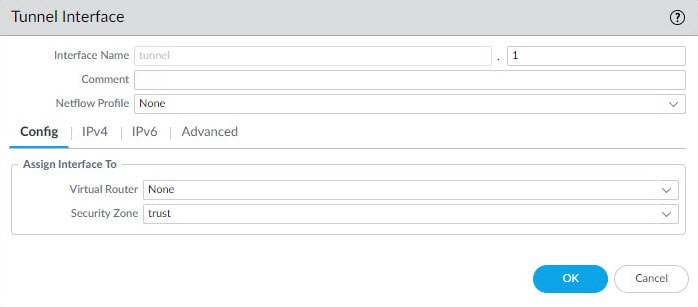
In this step we will create the tunnel interface that will be used by the virtual router to send the traffic destined to the remote encryption domains (proxy IDs). This tunnel interface does not have to have an IP address unless you use a feature such as Policy Based Forwarding which requires an IP address to be assigned to the tunnel interface.
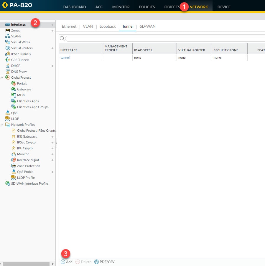
As a minimum, we need define an interface ID, in our example we are going to define ID 1. We also need to associate this interface to a virtual router and a security zone. We can do this from the tunnel interface Config tab or from the virtual router and security zone settings.
In our example here we will only select the security zone called trust, and then we will associate the tunnel interface tunnel.1 to the default virtual router from the virtual router section in the next step.
Go to Network > Interfaces > Add
Step 5: Virtual Routers
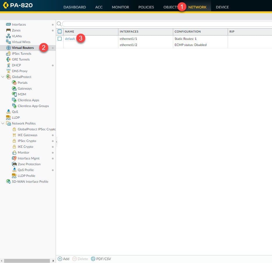
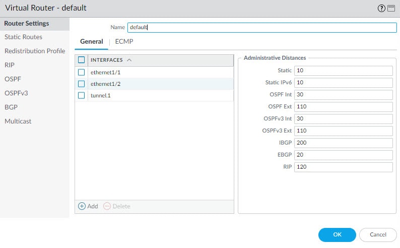
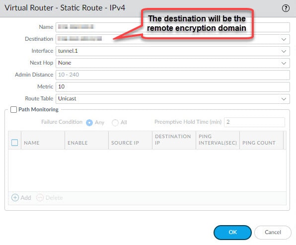
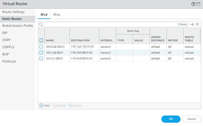
From the virtual router settings section we are going to associate the tunnel.1 interface we created in the previous step, and we will also create a static route to point the VPN traffic destined to the remote encryption domains to the tunnel.1 interface.
Go to Network > Virtual Routers > default
Click Add from the General tab and select the tunnel.1 interface, then go to Static Routes tab to add the remote encryption domains route(s) and associate that route to the tunnel.1 interface. Leave the Next Hop value to None.
In our example we defined three static routes for the three remote encryption domains behind the ASA.
Step 6: IPSec Tunnels
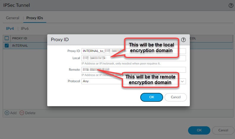
From the IPSec Tunnels section we will tie all the Phase 1 and 2 bits and pieces together. We will also define the local and remote encryption domains (proxy IDs) to change the default behaviour from route-based to policy-based VPN tunnel.
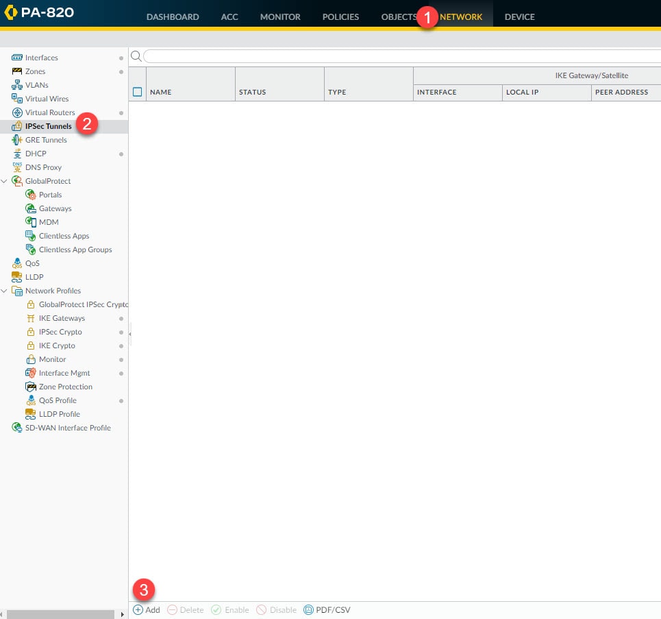
Go to Network > IPSec Tunnels > Add
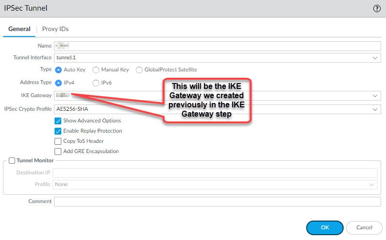
Give the IPSec tunnel a name, select the tunnel.1 interface, select the IKE Gateway we created in step 2, select the IPSec Crypto profile we created in step 3 and go to Proxy IDs tab and define the local and remote encryption domains to convert this tunnel from route-based to policy-based tunnel.
Step 7: Security Policies
The security policies configuration for the VPN tunnel depends on our existing security policies. Palo Alto firewalls have a couple of default rules, one is the intrazone-default and another is the interzone-default. The intrazone-default rule is used for the traffic traversing within the same zone, and it is set to Allow action by default. The interzone-default rule instead is used for the traffic traversing between the zones, for example, between trust and untrust, and this rule is set to Deny action by default.
The IKE negotiation traffic between the Palo Alto and the ASA will be traversing within the same zone, in our case, it will be sourcing from untrust destined to untrust. Similar for the traffic between the encryption domains, in our case both the local encryption domains interface and remote encryption domains interfaces (tunnel.1) belong to the same security zone, trust.
This means that if we are leveraging the default rule intrazone-default which by default will allow the traffic traversing within the same zone, then we don't have to add any security policy to make our VPN tunnel functional.
However, if we have a deny rule on top of the intrazone-default rule, or if we have overridden the intrazone-default rule action to deny instead of allow, then we need to create a couple of rules to allow the IKE negotiation traffic and the encryption domains traffic between the Palo Alto and ASA firewalls.
Go to Policies > Security
In the example below we are leveraging the intrazone-default rule, and this rule will allow both the IKE negotiation traffic (untrust to untrust) and the encryption domains traffic (trust to trust).
In this other example instead, we have a deny rule on top of the intrazone-default rule, so we have to configure two rules to allow IKE negotiation and encryption domains traffic between the Palo Alto and the ASA. Instead of creating a new separate rule to allow the encryption domains traffic, we added the trust zone to the existing Allow_IN_OUT rule. This will allow the encryption domains traffic between the two ends.
For the IKE negotiation traffic we created another rule called Allow_VPN_Peers and defined the remote ASA public IP address as the destination address. We also defined the ike and ipsec-esp as the applications from the Application tab. The source IP address can be any, or if we want to be more specific we could define the Palo Alto outside interface IP address.
Step 8: Verification
As you could see, we did not cover anything regarding NAT exemption (Identity NAT). That's because our NAT policy is configured to only match the traffic from trust to untrust zones, so it won't affect the IKE negotiation or the encryption domains traffic since again that traffic will be flowing within its related security zone.
This wraps up our post about Palo Alto site-to-site VPN with Cisco ASA configuration.
Thank you for reading!
